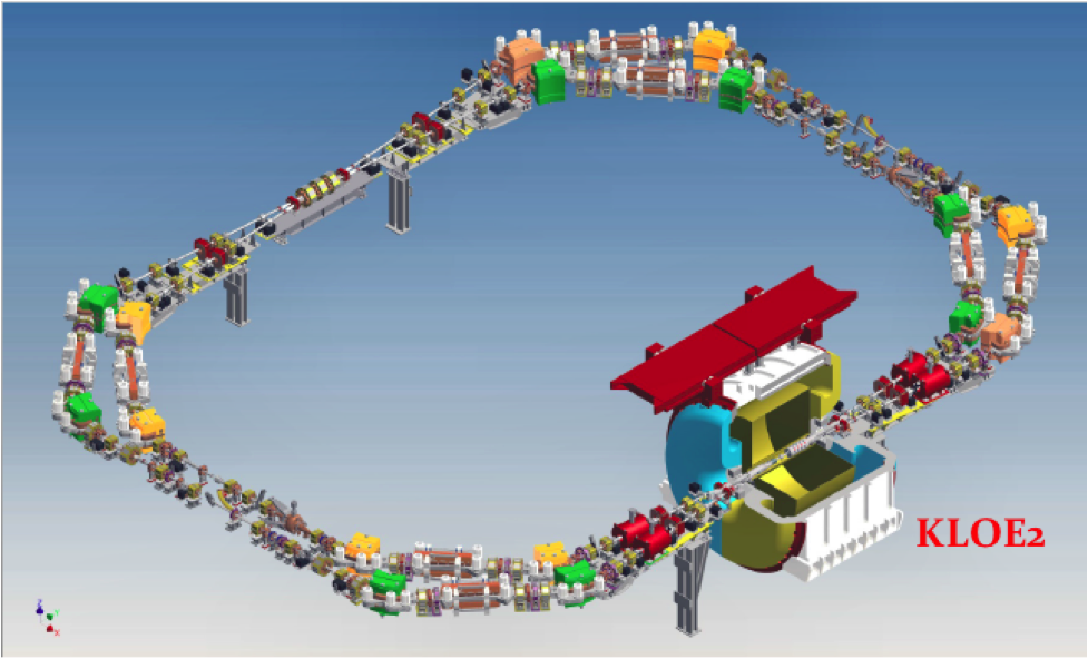
Electron and positron beams circulate in 2 separate rings of ~100 m circumference in opposite directions. Beams travel in the same beam pipe only in the Interaction Region (~1.5 m) IR1 and collide in only 1 Interaction Point, where the KLOE2 detector is installed. The beams collide at a large horizontal crossing angle and the Interaction Region design is based on the “Crab-waist” scheme.
In the opposite Interaction Region IR2 the beams are separated by vertical correctors and travel in specially designed separated chambers.
Each ring, made of a Long and a Short half, has 4 Wigglers to increase beam radiation and damping. Injection takes place in the long straight section and the 368 MHz RF cavity is placed in the short one.
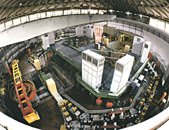
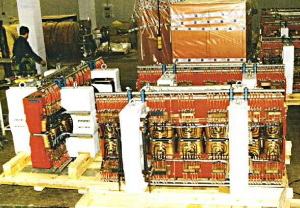
The DAFNE Main Rings during installation (December 1996).
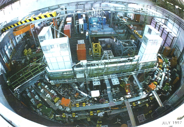
The DAFNE Main Rings at the end of the installation (July 1998).
Due to the peculiar geometry of the crossing in the horizontal plane, each Main Ring of the DAFNE collider consists of two 180 degrees bends of different length, the “short arc” and the “long arc”.
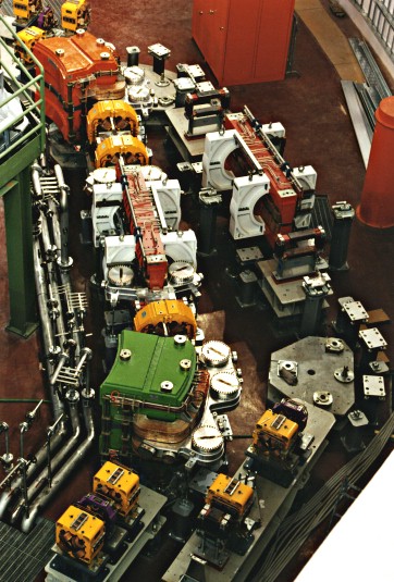 First assembly test of the short achromat with long vacuum vessel, dipoles, quadrupoles and wiggler.
The original design of the Main Rings had vanishing dispersion at the crossing points and in all the four straight sections at 90 degrees with respect to the interaction regions. The arcs consisted of two cells, each composed of 2 dipoles, 3 quadrupoles, 2 sextupoles for chromaticity correction and one wiggler to increase the total radiation damping. In the long arc the dipoles bend the beam by 95 degrees, in the short one by 85 degrees. Further improvements in the lattice design have led to non-vanishing dispersion in the straight section of the long arc, where injection is performed. The short arc has small dispersion to avoid synchro-betatron coupling in the R.F. cavity.
The dipoles are C-shaped with flat poles. In each cell one of the two dipoles has parallel ends, while the other is a sector type one. The magnets have a rather large gap and pole width to provide a large acceptance for the relatively high beam emittance. The quadrupoles and sextupoles are also large, in order to cope with the peculiar design of the vacuum chamber in the arc, described in the following.
 “Parallel end short” dipole.
“Sector-like short” dipole.
 Large quadrupole prototype.
Large sextupole prototype.
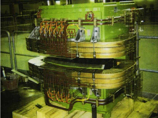
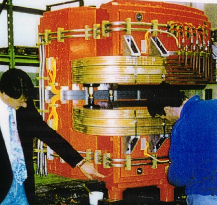
The wigglers used to double the synchrotron radiation power emitted by the beam are conventional electromagnets, each made of five central poles and two shorter end poles. The peak field in the poles is 1.85 T, to be compared to the 1.2 T in the bending magnet.
The DAFNE wigglers after delivery.
In the long arc, the straight section between the two dipole cells is used for injection. A first septum magnets, consisting of a thin copper sheet of 1.5 mm thickness, and carrying 2000 A direct current, separates the vacuum vessel of the ring from the injection channel coming from the Accumulator, and performs the final 2 degrees deflection of the injected beam. Two pulsed kickers provide a local single turn closed orbit deformation, which merges the injection pulses into the already stored beam. 10 quadrupoles in this section are used to control the betatron tunes of the ring and to optimise the phase advance between the kickers and the injection septum.
The 2 degrees injection septa into the DAFNE Main Rings.
The 34 degrees injection septum into the DAFNE Main Rings.
The structure of the straight section in the short arc is similar to the long arc one, with 7 quadrupoles: the R.F cavity of the ring is placed in this straight.
All the wigglers in the same ring and some dipoles are connected in series, while all the other magnets have their independent power supply, in order to ensure the maximum flexibility in the operation of the machine.
There are 216 magnets in the Main Rings of 22 different kinds, including normal conducting electromagnets, superconducting solenoids and permanent magnet quadrupoles, powered by 290 independent power supplies.
The pulsed systems under vacuum (“kickers”) in the DAFNE Accumulator and Main Rings consists of a couple of coils fed by a pulsed power supply (completely designed and built at LNF) capable of delivering 200 ns pulses of 3 KA peak current at 35 KV at a maximum repetition rate of 50 Hz. The stability of the system is excellent: the peak current is stable within ±0.3% and jitters by less than 3 ns; the maximum reverse current is less than 2.5%. The Main Rings kickers have been redesigned for the SIDDHARTA Run in order to improve their performances, achieving a better uniformity of the deflecting field and a lower contribution to the ring total coupling impedance.
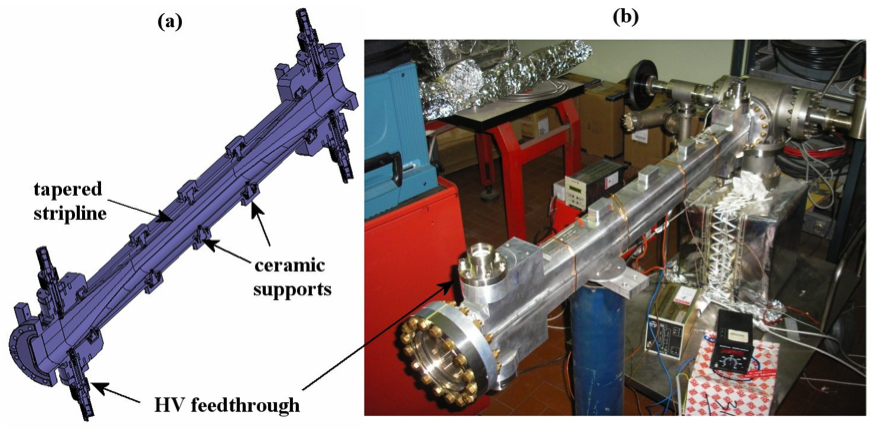 The new Main Rings stripline kicker.
Particular care has been taken in the design of the Main Rings vacuum system, to cope with the very high radiation power emitted by the beam. At the original design current ~50 KW were dissipated in each ring, under the constraint of keeping the average pressure in the chamber below 1 nTorr for beam lifetime reasons. In addition, the requirement of low beam generated background to the detectors in the interaction regions calls for lower pressure near the interaction points. In order to achieve this performance, a special vacuum chamber has been designed in the arcs, consisting of three parts, the central one around the beam separated from two “antechambers” by means of a narrow slot allowing the passage of photons radiated by the electron beam in the wigglers. The same arrangement, but with only one antechamber towards the outside of the ring has been adopted for the bending magnet.
The heart of the DAFNE pumping system is a special titanium sublimation pump. The necessity of making available a large amount of titanium has led to the design of a new type of source, composed of 12 titanium filaments, properly assembled and cabled on an ultra-vacuum compatible flanged support.
The requirement of keeping the pressure in the interaction region below 10-9 mbar with up to 5 A current in each ring together with the extremely poor availability of space in these regions resulted in the design of a high capacity non evaporable getter pump. Using a new type of syntherized getter, a prototype has been realized and tested with excellent results both in the pumping speed (2000 l/s) and in pumped gas amount (90 mbar.l) at each pump activation.
Vacuum vessel cross sections in the Main Ring arcs.
The arc cells are the “hottest” region from the point of view of emitted synchrotron radiation power. The vacuum vessel in each cell has been designed as a single piece ~10 m long aluminum chamber, including the two dipoles and the straight section with the wiggler in between. The radiation from the dipoles and the wiggler travels through the slots to the antechamber, where it hits special water-cooled copper absorbers.
The first vacuum vessel of the Main Ring achromats.
 Schematic of the achromat vacuum vessel with synchrotron radiation absorbers.
Near each synchrotron radiation absorber, where the gas load is concentrated, there is a titanium sublimation pump with a pumping velocity of ~2000 litres per second, and a sputter ion pump to extract those kind of gases which are not efficiently pumped by the sublimators. Special NEG pumps are foreseen in the interaction regions, where a lower pressure is needed to avoid excessive backgrounds to the experiments.
The radiofrequency system of each ring consists of a normal conducting single cell cavity running at 368 MHz on the 120th harmonic of the revolution period. Each cavity is fed by a 150 KW/cw klystron, protected against the reflected cavity power by a ferrite circulator. In order to reduce the interaction of the beam with the high order modes of the cavity, the latter is equipped with long tapered beam tubes and three waveguides to couple out the parasitic modes that are then dissipated into external 50 Ohm loads by means of special broadband transitions between the waveguides and coaxial vacuum feedthroughs.
The prototype Main Ring radiofrequency cavity under construction.
The R.F. cavity of the Main Rings.
The high order mode absorber with the broadband transition from the waveguide to coaxial external load.
The central body of the R.F. cavity is obtained from a single forged OFHC copper billet and the internal surface is fully manufactured with an automatic milling machine.
The basic design choice of achieving the required luminosity with a large total current distributed over a large number of bunches makes the operation very critical with respect to longitudinal coupled bunch instabilities caused by parasitic higher order modes in the ring, mainly in the R.F. cavity. These instabilities have been identified as a potentially severe limit to the ultimate achievable luminosity. Even though the high order modes in the cavity are strongly damped by the waveguides absorbers, the probability for a damped high order mode to cross a coupled bunch mode frequency is large and, due to the large total current, the growth rate of unstable modes can be stronger than the radiation damping by up to two orders of magnitude.
The required additional damping is provided by a longitudinal feedback system, based on digital signal processors (DSP), which acts on each bunch individually. The digital section has been constructed at SLAC in the framework of a collaboration with the SLAC-LBL PEPII group on feedback systems for the next generation of “factories” with intense beams and a large number of bunches.
The active element of the feedback chain for DAFNE is a special overdamped cavity running at 1.2 GHz (3.25 times the main R.F. frequency). The cavity has a diameter of 20 cm and is 7.2 cm long. To obtain the large required bandwidth (~180 MHz for operation with 120 bunches), the cavity is loaded with 6 ridged waveguides followed by broadband transitions.
CAD view of the longitudinal feedback kicker cavity.
Prototype longitudinal feedback kicker cavity.
Additional instrumentation for the Main Rings consists in a distributed orbit correction system made of button pick-ups, striplines and horizontal/vertical correctors, sensitive to the beam position also in a single-turn mode. Synchrotron radiation monitors and single bunch current detectors will also be available for beam diagnostics purposes. A system of skew quadrupoles is foreseen to control the beam coupling at the interaction point, as well as a beam deflection system to separate the beams during injection and to finely control the superposition of the beams at interaction.
The “Rectangular” corrector for the Main Rings.
The double function corrector for the Main Rings: it is at the same time a horizontal/vertical dipole and a skew quadrupol.
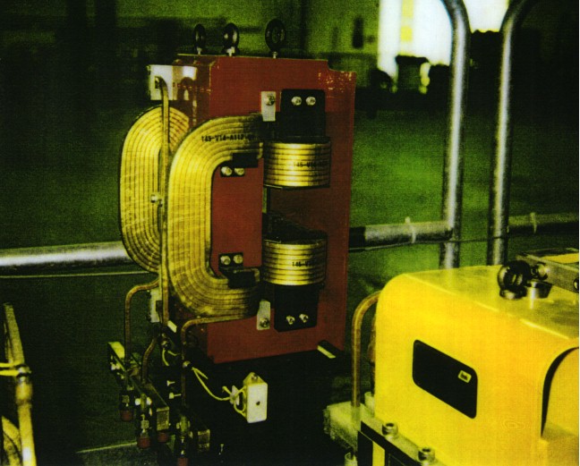
Special dipole correctors are needed near the splitter, due to the close proximity of the two rings. A couple of “Lambertson” correctors is placed between the solenoid compensator magnet and the splitter: they are used both to correct the closed orbit at the interaction point and to create vertical separation of the beams at injection. The “C” correctors, so called because of their unusual shape, correct the orbit deviation occurring when the crossing angle of the beams at the interaction points is made different from the nominal one. This feature has given great flexibility for the design of the interaction regions. The total crossing angle has been changed from 25 mrad, used until 2006, to the value of 50 mrad used for the “Crab-waist” configuration.
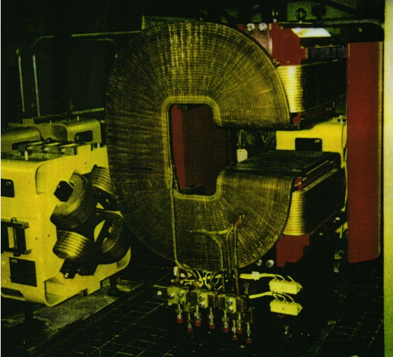
 The “Lambertson” corrector. A couple of these correctors is placed in the interaction region, where the vacuum chamber of the two rings are very near. The yoke is of the “C” type with an iron shield towards the symmetry axis of the interaction section, to avoid interference with the other corrector.
The “C” corrector of the Main Rings: it is used when the crossing angle of the beams at the interaction point is changed from the nominal one (25 mrad total).
The luminosity is measured both by the experimental detectors through the rate of well-known electromagnetic reactions, and by a special system of counters measuring the rate of single beam-beam bremsstrahlung produced at the interaction points.